TikZ Figures
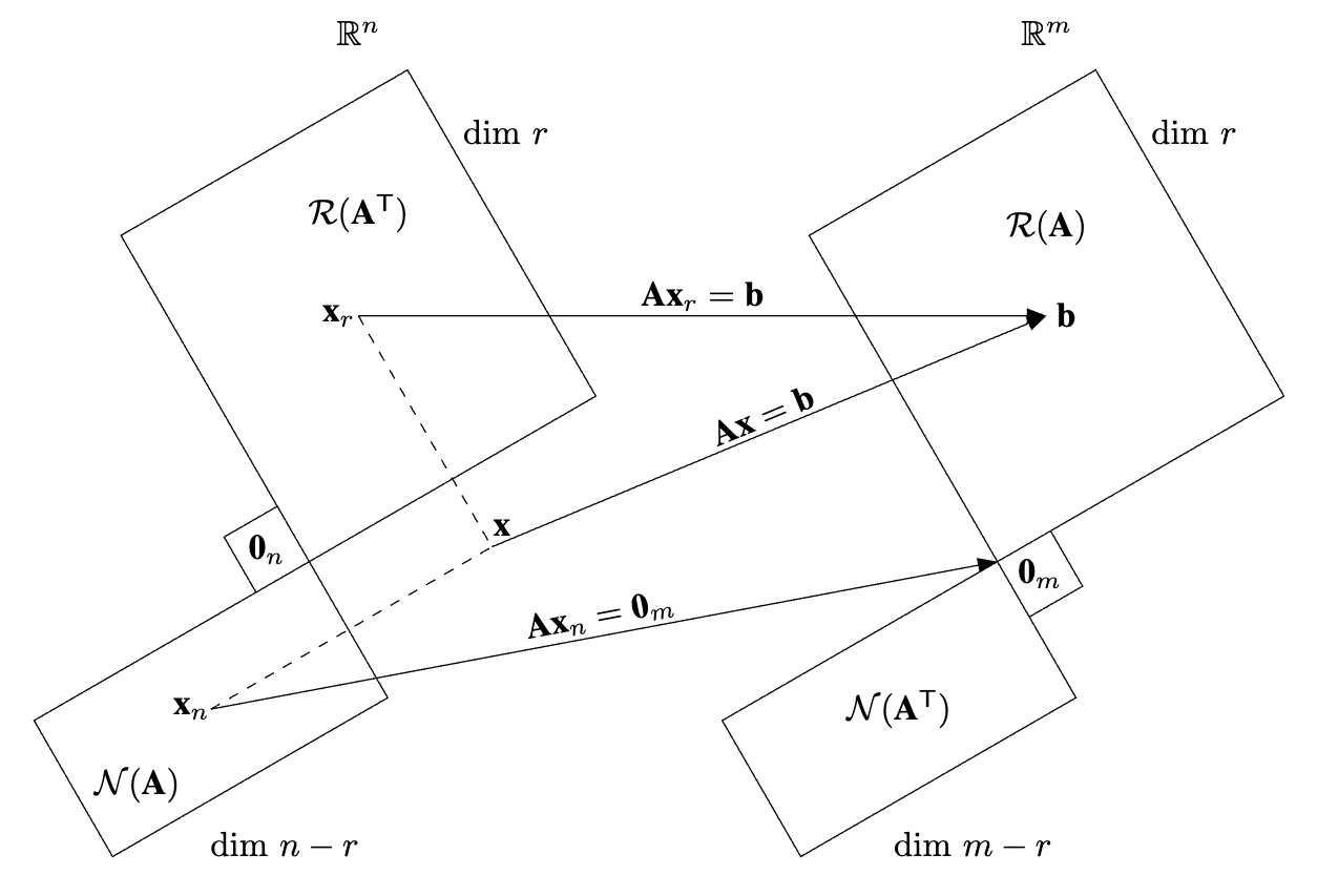
Subspaces
-

-
Required Math Formatting Packages:
\usepackage{amsmath}
\usepackage{amssymb}
\DeclareMathAlphabet{\mbf}{OT1}{ptm}{b}{n}
\providecommand{\trans}{{\ensuremath{\mathsf{T}}}}
Required Tikz Packages and Libraries:
\usepackage{tikz}
\usetikzlibrary{positioning, arrows.meta, calc, intersections}
TikZ Code:
\begin{tikzpicture}
    % ------------------------------------------------------------------------------------ %
    %                                Required Tikz Libraries
    % ------------------------------------------------------------------------------------ %
    % \usetikzlibrary{positioning, arrows.meta, calc, intersections}
    % 1) arrows.meta is used for arrow tips
    % 2) positioning is used for relative positioning of nodes
    % 3) calc is used for coordinate calculations
    % 4) intersections is used to find the intersection of two paths

    % ------------------------------------------------------------------------------------ %
    %                           Define Constant Dimension Parameters
    % ------------------------------------------------------------------------------------ %
    \def\blockAngle{30}                                 % Rotation of the block
    \def\blockAngleMirrored{\blockAngle + 90}           % Mirror angle about x-axis
    \def\blockXshift{7}                                 % Shift in x-direction

    \def\dashedLineAngle{\blockAngle - 90}              % Angle of lines intersecting at x
    \def\dashedLineAngleMirrored{\blockAngle}           % Angle of lines intersecting at x

    \def\arrowTipLength{2mm}                            % Length of arrow tip ->
    \def\arrowTipWidth{1.5mm}                           % Width of arrow tip ->
    \def\arrowTextYshift{2pt}                           % Shift text above the arrow

    \pgfmathsetmacro{\cosBlockAngle}{cos(\blockAngle)}  % Trig for finding corners
    \pgfmathsetmacro{\sinBlockAngle}{sin(\blockAngle)}  % Trig for finding corners

    % ------------------------------------------------------------------------------------ %
    %                           Define Objects and Styles
    % ------------------------------------------------------------------------------------ %
    % Setting custom arrow style (uses package arrows.meta)
    \tikzset{
        myarrow/.style = {->, -{Triangle[length=\arrowTipLength, width=\arrowTipWidth]}}
    }

    % ------------------------------------------------------------------------------------ %
    %                            Start Drawing the Diagram
    % ------------------------------------------------------------------------------------ %
    % Define the coordinates of the corners of the left space
    \coordinate (left_center) at (0, 0);
    \coordinate (xr_corner)   at (1, 5);
    \coordinate (xn_corner)   at (-2, -3);

    % Shift the coordinates to the right to make the right space
    \coordinate (right_center) at ($(left_center) + (\blockXshift, 0)$);
    \coordinate (b_corner)     at ($(xr_corner)   + (\blockXshift, 0)$);
    \coordinate (NAT_corner)   at ($(xn_corner)   + (\blockXshift, 0)$);

    % Draw the x_r space
    \begin{scope}[rotate around={\blockAngle:(left_center)}]
        \draw (left_center) rectangle (xr_corner);
        \node at ($(left_center)!0.5!(xr_corner)$) (x_r_space) {};
    \end{scope}

    % Draw the x_n space
    \begin{scope}[rotate around={\blockAngleMirrored:(left_center)}]
        \draw (left_center) rectangle (xn_corner);
        \node at ($(left_center)!0.5!(xn_corner)$) (x_n_space) {};
    \end{scope}

    % Draw the b space
    \begin{scope}[rotate around={\blockAngle:(right_center)}]
        \draw (right_center) rectangle (b_corner);
        \node at ($(right_center)!0.5!(b_corner)$) (b_space) {};
    \end{scope}

    % Draw the N(A') space
    \begin{scope}[rotate around={\blockAngleMirrored:(right_center)}]
        \draw (right_center) rectangle (NAT_corner);
        \node at ($(right_center)!0.5!(NAT_corner)$) (NAT_space) {};
    \end{scope}

    % Define the dashed paths to find the intersection point x
    \path[name path=path_r] (x_r_space.center) -- ++(\dashedLineAngle:5cm);
    \path[name path=path_n] (x_n_space.center) -- ++(\dashedLineAngleMirrored:5cm);

    % Find the intersection point x
    \path[name intersections={of=path_r and path_n, by=x}];

    % Draw dashed lines up to the intersection point x
    \draw[dashed] (x_r_space.center) -- (x);
    \draw[dashed] (x_n_space.center) -- (x);

    % Draw the arrows
    \draw[myarrow] (x_r_space.center) -- (b_space.center)      node[midway, sloped, above, yshift=-\arrowTextYshift] {$\mbf{A}\mbf{x}_{r} = \mbf{b}$};
    \draw[myarrow] (x_n_space.center) -- (right_center.center) node[midway, sloped, above, yshift=-\arrowTextYshift] {$\mbf{A}\mbf{x}_{n} = \mbf{0}_{m}$};
    \draw[myarrow] (x.center)         -- (b_space.center)      node[midway, sloped, above, yshift=-\arrowTextYshift] {$\mbf{A}\mbf{x} = \mbf{b}$};

    % Label the Spaces
    \node[above=0.6cm of x_r_space]                  {$\mathcal{R}(\mbf{A}^{\trans})$};
    \node[below=0.35cm of x_n_space, xshift=-0.75cm] {$\mathcal{N}(\mbf{A})$};
    \node[above=0.47cm of b_space]                   {$\mathcal{R}(\mbf{A})$};
    \node at (NAT_space)                             {$\mathcal{N}(\mbf{A}^{\trans})$};

    \node at (x_r_space) [xshift=-0.2cm]              {$\mbf{x}_{r}$};
    \node at (x_n_space) [xshift=-0.2cm]              {$\mbf{x}_{n}$};
    \node at (b_space)   [xshift=0.2cm]               {$\mbf{b}$};
    \node at (x)         [xshift=0.1cm, yshift=0.2cm] {$\mbf{x}$};

    \node[above=2.5cm of x_r_space, xshift=0cm]                   {$\mathbb{R}^{n}$};
    \node[above=2.5cm of x_r_space, xshift=0cm + \blockXshift cm] {$\mathbb{R}^{m}$};

    \node[above=1.5cm of x_r_space, xshift=1.5cm]                   {$\dim \, r$};
    \node[above=1.5cm of x_r_space, xshift=1.5cm + \blockXshift cm] {$\dim \, r$};
    \node[below=1cm of x_n_space, xshift=0.75cm]                    {$\dim \, n - r$};
    \node[below=1cm of x_n_space, xshift=0.75cm + \blockXshift cm]  {$\dim \, m - r$};

    % Draw the 0_n
    \coordinate (0_n_corner) at ($(left_center) + (-\cosBlockAngle, 0.25)$);
    \begin{scope}[rotate around={\blockAngle:(left_center)}]
        \draw (left_center) rectangle (0_n_corner);
        \node at ($(left_center)!0.5!(0_n_corner)$) (O_n) {$\mbf{0}_{n}$};
    \end{scope}

    % Draw the 0_m
    \coordinate (0_m_corner) at ($(right_center) + (\cosBlockAngle, -0.25)$);
    \begin{scope}[rotate around={\blockAngle:(right_center)}]
        \draw (right_center) rectangle (0_m_corner);
        \node at ($(right_center)!0.5!(0_m_corner)$) (O_m) {$\mbf{0}_{m}$};
    \end{scope}
\end{tikzpicture}
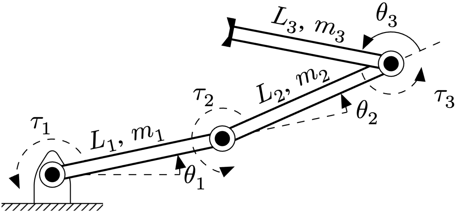
Three-Link Robotic Manipulator
-

-
Required Packages and Libraries:
\usepackage{tikz}
\usetikzlibrary{patterns, arrows.meta}
TikZ Code:
\begin{tikzpicture}[auto, node distance=2cm]
    % Modified from
    % https://texample.net/tikz/examples/three-link-annotated/

    % ------------------------------------------------------------------------------------ %
    %                           Define Constant Dimension Parameters
    % ------------------------------------------------------------------------------------ %
    % Define a variable as a length
    % Input:
    %   1 Variable name
    %   2 Value
    %
    % Example:
    %   \nvar{\varx}{2cm}
    \newcommand{\nvar}[2]{\newlength{#1}\setlength{#1}{#2}}

    \def\arrowTipLength{2mm}             % Length of arrow tip ->
    \def\arrowTipWidth{1.5mm}            % Width of arrow tip ->

    % Define a constants for drawing
    \nvar{\dg}{0.2cm}
    \def\dw{0.25}
    \def\dh{0.4}
    \nvar{\ddx}{1.1cm}

    % Define the kinematic parameters of the robot
    \def\Lscale{1.5}
    \def\thetaone{12}
    \def\Lone{\Lscale*1.6}
    \def\thetatwo{12}
    \def\Ltwo{\Lscale*1.7}
    \def\thetathree{145}
    \def\Lthree{\Lscale*1.5}

    % ------------------------------------------------------------------------------------ %
    %                           Define Objects and Styles
    % ------------------------------------------------------------------------------------ %
    % Setting custome arrow style (uses package arrows.meta)
    \tikzset{
        myarrow/.style = {->, -{Triangle[length=\arrowTipLength, width=\arrowTipWidth]}}
    }

    % Define commands for links, joints and such
    \def\link{\draw [double distance=1.5mm, thick] (0,0)--}
    \def\joint{
        \filldraw [fill=white] (0,0) circle (5pt);
        \fill[black] circle (3pt);
    }

    \def\grip{
        \draw[ultra thick](0cm,\dg)--(0cm,-\dg);
        \fill (0cm,   \dg) -- +(0.5\dg, 0cm) -- +(0pt, -5.5pt);
        \fill (0cm,  -\dg) -- +(0.5\dg, 0cm) -- +(0pt, 5.5pt);
    }

    \def\robotbase{
        \draw[rounded corners=4pt] (-\dw,-\dh)-- (-\dw, 0) -- (0,\dh)--(\dw,0)--(\dw,-\dh);
        \draw (-0.7,-\dh)-- (0.7,-\dh);
        \fill[pattern=north east lines] (-0.7,-0.5) rectangle (0.7,-\dh);
    }
    % Draw an angle annotation
    % Input:
    %   1 Angle
    %   2 Label
    % Example:
    %   \angann{30}{$\theta_1$}
    \newcommand{\angann}[8]{
        \begin{scope}[black]
            \draw [dashed, black] (0,0) -- (#5*\ddx,0pt);
            \draw [myarrow] (#3*\ddx,0pt) arc (0:#1+#6:#3*\ddx+#7);
            \node at (#1/2-2:\ddx+#4)[yshift=#8] {#2};
        \end{scope}
    }

    \newcommand{\jointTorque}[9]{
        \begin{scope}[rotate=#6]
            \draw [myarrow,dashed] (#1,#2) arc (#3:#4:#5) node[midway, above, xshift=#8, yshift=#9]{#7};
        \end{scope}
    }
    % Draw line annotation
    % Input:
    %   1 Line offset (optional)
    %   2 Line angle
    %   3 Line length
    %   5 Line label
    % Example:
    %   \lineann[1]{30}{2}{$L_1$}
    \newcommand{\lineann}[7][0.5]{
        \begin{scope}[rotate=#2, black,inner sep=2pt]
            \node[coordinate] (a) at (0,#1) {};
            \node[coordinate] (b) at (#3,#1) {};
            \path (a) -- node[black,rotate=#5,xshift=#6, yshift=#7] {#4} (b);
        \end{scope}
    }

    % ------------------------------------------------------------------------------------ %
    %                            Start Drawing the Diagram
    % ------------------------------------------------------------------------------------ %
    \robotbase
    \angann{\thetaone}{$\theta_1$}{1.6pt}{25pt}{1.6pt}{0pt}{-12pt}{-5pt}
    \lineann[0.1]{\thetaone}{\Lone}{$L_1$, $m_1$}{\thetaone}{15pt}{-1pt}
    \jointTorque{14pt}{0pt}{0}{180 + \thetaone}{14pt}{\thetaone}{$\tau_1$}{0}{-1pt}
    \link(\thetaone:\Lone);
    \joint
    \begin{scope}[shift=(\thetaone:\Lone), rotate=\thetaone]
        \jointTorque{12pt}{0pt}{0}{270}{12pt}{\thetatwo}{$\tau_2$}{4pt}{5pt}
        \angann{\thetatwo}{$\theta_2$}{1.6pt}{28pt}{1.6pt}{0pt}{-13pt}{-6pt}
        \lineann[0.1]{\thetatwo}{\Ltwo}{$L_2$, $m_2$}{\thetatwo + \thetaone}{15pt}{-1pt}
        \link(\thetatwo:\Ltwo);
        \joint
        \begin{scope}[shift=(\thetatwo:\Ltwo), rotate=\thetatwo]
            \angann{\thetathree}{$\theta_3$}{0.4pt}{-12pt}{0.75pt}{-15pt}{0pt}{0}
            \lineann[-0.7]{\thetathree}{\Lthree}{$L_3$, $m_3$}{\thetathree + \thetatwo + \thetaone - 180}{15pt}{-4pt}
            \draw [dashed, black,rotate=\thetathree] (0,0) -- (1.2\ddx,0pt);
            \jointTorque{12pt}{0pt}{0}{185}{12pt}{\thetathree}{$\tau_3$}{23pt}{-9pt}
            \link(\thetathree:\Lthree);
            \joint
            \begin{scope}[shift=(\thetathree:\Lthree), rotate=\thetathree]
                \grip
            \end{scope}
        \end{scope}
    \end{scope}
\end{tikzpicture}
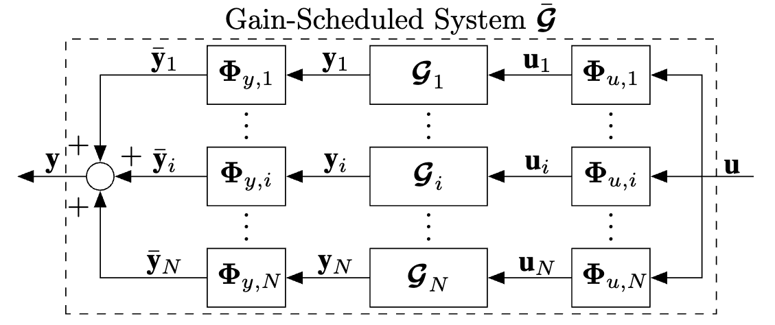
Gain-Scheduled System
-

-
Required Math Formatting Packages:
\usepackage{bm}
\usepackage{amsmath}
\usepackage{amssymb}
\DeclareMathAlphabet{\mbf}{OT1}{ptm}{b}{n}
\providecommand{\trans}{{\ensuremath{\mathsf{T}}}}
\providecommand{\mbs}[1]{\ensuremath{\boldsymbol{#1}}}
Required Tikz Packages and Libraries:
\usepackage{tikz}
\usetikzlibrary{positioning, patterns, arrows.meta, calc}
TikZ Code:
\begin{tikzpicture}
    % ------------------------------------------------------------------------------------ %
    %                                Required Tikz Libraries
    % ------------------------------------------------------------------------------------ %
    % 1) arrows.meta is used for arrow tips
    % 2) positioning is used for relative positioning of nodes
    % 3) calc is used for coordinate calculations
    % ------------------------------------------------------------------------------------ %
    %                           Define Constant Dimension Parameters
    % ------------------------------------------------------------------------------------ %
    \def\blockWidth{4em}                 % Width of Control block
    \def\blockHeight{2em}                % Height of Control block
    \def\blockVerticalSpacing{0.5cm}     % Vertical spacing between parallel blocks

    \def\arrowTipLength{2mm}             % Length of arrow tip ->
    \def\arrowTipWidth{1.5mm}            % Width of arrow tip ->


    \def\smallArrowLength{1cm}           % Length of small arrows used for input/output/scheduling
    \def\smallArrowStretch{1.5}          % Stretch the length of the small arrows by this amount

    \def\dashedRectangleHeight{3.3cm}
    \def\dashedRectangleWidth{7.8cm}
    \def\dashedRectanglCenterXShift{4.5mm}
    \def\dashedRectanglCenterYShift{0.0cm}

    \def\parallelWidthStretch{3.4}       % Stretch the width of the parallel blocks by this amount

    % ------------------------------------------------------------------------------------ %
    %                           Define Objects and Styles
    % ------------------------------------------------------------------------------------ %
    % Sum and multiplication nodes
    \tikzset{
        sum/.style  = {draw, fill=none, circle, node distance=1cm},
    }

    % Control block
    \tikzset{
        block/.style = {draw, fill=none, rectangle,
                        minimum height=\blockHeight, minimum width=\blockWidth},
        squareblock/.style = {draw, fill=none, rectangle,
                        minimum height=\blockHeight, minimum width=\blockHeight, text width=\blockHeight, align=center},
    }

    % Points
    \tikzset{
        tmp/.style    = {coordinate},
        input/.style  = {coordinate},
        output/.style = {coordinate}
    }

    % Pin style to edge of block
    \tikzset{
        pinstyle/.style = {pin edge={to-,thin}}
    }

    % Setting custome arrow style (uses package arrows.meta)
    \tikzset{
        myarrow/.style = {->, -{Triangle[length=\arrowTipLength, width=\arrowTipWidth]}}
    }

    % ------------------------------------------------------------------------------------ %
    %                               Start Drawing the Diagram
    % ------------------------------------------------------------------------------------ %
    % Make the input node and the sum
    \node [input] (rinput) {};
    \node [sum, right of=rinput] (sumSl) {};

    % Make the parallel G1, Gi, GN blocks
    \node [block, right=\parallelWidthStretch*\smallArrowLength of sumSl.west](sumSl) (Gi) {$\bm{\mathcal{G}}_{i}^{}$};
    \node [block, above=\blockVerticalSpacing of Gi.north, anchor=south] (G1) {$\bm{\mathcal{G}}_{1}^{}$};
    \node [block, below=\blockVerticalSpacing of Gi.south, anchor=north] (GN) {$\bm{\mathcal{G}}_{N}^{}$};

    % Draw the \vdots between G1 and Gi and Gi and GN
    \node [below=\blockVerticalSpacing/2 of G1, yshift=3pt, anchor=center] (vdots) {$\vdots$};
    \node [below=\blockVerticalSpacing/2 of Gi, yshift=3pt, anchor=center] (vdots) {$\vdots$};

    % Make the multiplication nodes across G1, Gi, GN blocks
    \node [squareblock, right=\smallArrowLength of G1.east] (sum1r) {$\mbs{\Phi}_{u, 1}$};
    \node [squareblock, left=\smallArrowLength  of G1.west] (sum1l) {$\mbs{\Phi}_{y, 1}$};

    \node [squareblock, right=\smallArrowLength of Gi.east] (sumir) {$\mbs{\Phi}_{u, i}$};
    \node [squareblock, left=\smallArrowLength  of Gi.west] (sumil) {$\mbs{\Phi}_{y, i}$};

    \node [squareblock, right=\smallArrowLength of GN.east] (sumNr) {$\mbs{\Phi}_{u, N}$};
    \node [squareblock, left=\smallArrowLength  of GN.west] (sumNl) {$\mbs{\Phi}_{y, N}$};

    % Draw the \vdots between multiplication blocks
    \path let \p1 = ($(G1)!0.5!(Gi)$),
                \p2 = (sum1r)
                in node[yshift=3pt] at (\x2,\y1) {$\vdots$};
    \path let \p1 = ($(G1)!0.5!(Gi)$),
                \p2 = (sum1l)
                in node[yshift=3pt] at (\x2,\y1) {$\vdots$};
    \path let \p1 = ($(Gi)!0.5!(GN)$),
                \p2 = (sumir)
                in node[yshift=3pt] at (\x2,\y1) {$\vdots$};
    \path let \p1 = ($(Gi)!0.5!(GN)$),
                \p2 = (sumil)
                in node[yshift=3pt] at (\x2,\y1) {$\vdots$};

    % Make the node across the parallel G1, Gi, GN blocks
    \node [tmp, right=\parallelWidthStretch*\smallArrowLength - 6pt of Gi.east] (sumSr) {};

    % Connect the blocks and the sum/mult nodes
    \draw [myarrow] (G1) -- node[above, xshift=0.1cm, yshift=-0.09cm]{$\mbf{y}_1$}(sum1l);
    \draw [myarrow] (sum1r) -- node[above, xshift=0.1cm, yshift=-0.09cm]{$\mbf{u}_1$}(G1);

    \draw [myarrow] (Gi) -- node[above, xshift=0.1cm, yshift=-0.09cm]{$\mbf{y}_i$}(sumil);
    \draw [myarrow] (sumir) -- node[above, xshift=0.1cm, yshift=-0.09cm]{$\mbf{u}_i$}(Gi);

    \draw [myarrow] (GN) -- node[above, xshift=0.1cm, yshift=-0.09cm]{$\mbf{y}_N$}(sumNl);
    \draw [myarrow] (sumNr) -- node[above, xshift=0.1cm, yshift=-0.09cm]{$\mbf{u}_N$}(GN);

    % Create a temp node to branch off from sumSr
    \node [tmp, left=\smallArrowStretch*\smallArrowLength - 25pt of sumSr.center] (tmp1) {};

    % Draw parallel arrows to the RHS multiplication nodes
    \draw [myarrow] (tmp1) |- (sum1r);
    \draw [myarrow] (tmp1) -- (sumir);
    \draw [myarrow] (tmp1) |- (sumNr);

    % Draw parallel arrows from the LHS multiplication nodes and add + sign
    \draw [myarrow] (sum1l) -| (sumSl)node[at end, left, yshift= \arrowTipLength] {$+$};
    \draw [myarrow] (sumil) -- (sumSl)node[at end, above, xshift= \arrowTipLength] {$+$};
    \draw [myarrow] (sumNl) -| (sumSl)node[at end, left, yshift=-\arrowTipLength] {$+$};

    % Label \bar{y}
    \draw [] (sum1l.west) node[above, xshift=-\smallArrowLength/2, yshift=-0.09cm] {$\bar{\mbf{y}}_1$};
    \draw [] (sumil.west) node[above, xshift=-\smallArrowLength/2, yshift=-0.09cm] {$\bar{\mbf{y}}_i$};
    \draw [] (sumNl.west) node[above, xshift=-\smallArrowLength/2, yshift=-0.09cm] {$\bar{\mbf{y}}_N$};

    % Label u
    \draw [] (sumSr) -- (tmp1)node[at end, above, xshift=\smallArrowLength/2 - 4pt, yshift=-0.09cm] {$\mbf{u}$};

    % Label y
    \draw [myarrow] node[at end, above, xshift=\smallArrowLength/2 - 2pt, yshift=-0.09cm] {$\mbf{y}$} (sumSl.west) -- ([xshift=-\smallArrowLength+5pt] sumSl.west);

    % Calculate the midpoint coordinates between G1 and GN
    \node [tmp, below= -\dashedRectanglCenterYShift of Gi.center, xshift=-\dashedRectanglCenterXShift] (sumSr)(center) {};
    \draw[dashed] (center) ++(-\dashedRectangleWidth/2, -\dashedRectangleHeight/2) rectangle ++(\dashedRectangleWidth, \dashedRectangleHeight);
    \node[above, yshift=\dashedRectangleHeight/2 - 2pt] at (center) {Gain-Scheduled System $\bar{\bm{\mathcal{G}}}$};
\end{tikzpicture}
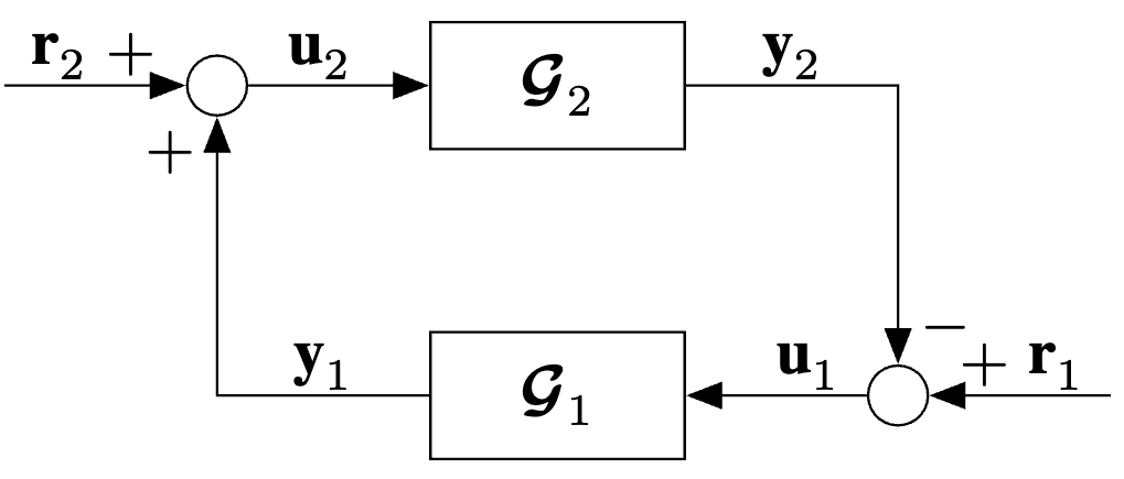
Negative Feedback Interconnection
-

-
Required Math Formatting Packages:
\usepackage{bm}
\usepackage{amsmath}
\usepackage{amssymb}
\DeclareMathAlphabet{\mbf}{OT1}{ptm}{b}{n}
Required Tikz Packages and Libraries:
\usepackage{tikz}
\usetikzlibrary{positioning, patterns, arrows.meta}
TikZ Code:
\begin{tikzpicture}
    % ------------------------------------------------------------------------------------ %
    %                                Required Tikz Libraries
    % ------------------------------------------------------------------------------------ %
    % 1) arrows.meta is used for arrow tips
    % 2) positioning is used for relative positioning of nodes

    % ------------------------------------------------------------------------------------ %
    %                           Define Constant Dimension Parameters
    % ------------------------------------------------------------------------------------ %
    \def\blockWidth{4em}           % Width of Control block
    \def\blockHeight{2em}          % Height of Control block
    \def\blockVerticalSpacing{1cm} % Vertical spacing between parallel blocks

    \def\arrowTipLength{2mm}       % Length of arrow tip ->
    \def\arrowTipWidth{1.5mm}      % Width of arrow tip ->


    \def\smallArrowLength{1cm}     % Length of small arrows used for input/output/scheduling
    \def\smallArrowStretch{1.5}    % Stretch the length of the small arrows by this amount
    \def\smallArrowShrink{0.8}     % Shrink the length of the small arrows by this amount

    % ------------------------------------------------------------------------------------ %
    %                           Define Objects and Styles
    % ------------------------------------------------------------------------------------ %
    % Control block
    \tikzset{
        block/.style = {draw, fill=none, rectangle,
                        minimum height=\blockHeight, minimum width=\blockWidth}
    }

    % Sum and multiplication nodes
    \tikzset{
        sum/.style  = {draw, fill=none, circle, node distance=1cm},
    }

    % Points
    \tikzset{
        tmp/.style    = {coordinate},
        input/.style  = {coordinate},
        output/.style = {coordinate}
    }

    % Pin style to edge of block
    \tikzset{
        pinstyle/.style = {pin edge={to-,thin}}
    }

    % Setting custome arrow style (uses package arrows.meta)
    \tikzset{
        myarrow/.style = {->, -{Triangle[length=\arrowTipLength, width=\arrowTipWidth]}}
    }

    % ------------------------------------------------------------------------------------ %
    %                               Start Drawing the Diagram
    % ------------------------------------------------------------------------------------ %
    % Make the Block
    \node [block] (Nonlinearity) {\(\bm{\mathcal{G}}_2\)};
    \node [block, below=\blockVerticalSpacing of Nonlinearity.south, anchor=north](G) {\(\bm{\mathcal{G}}_1\)};

    % Make temp nodes to draw input/output arrows
    \node [tmp, right=\smallArrowLength of G.east] (G_in) {};
    \node [tmp, left=\smallArrowLength  of G.west] (G_out) {};

    % Draw the sum node at G_in
    \node [sum, left=\smallArrowLength of Nonlinearity.west] (sum_node_up){};
    \node [sum, right=\smallArrowLength of G.east]           (sum_node_down){};

    % Draw input/output arrows between Nonlinearity and G
    \draw [myarrow](G) -| node[pos=0.25, above, yshift=-0.09cm]{$\mbf{y}_1$} (sum_node_up)node[at end, left, yshift=-\arrowTipLength] {$+$};
    \draw [myarrow](sum_node_down) -- (G)node[at end, above, xshift=\smallArrowLength/2 + 5, yshift=-0.09cm] {$\mbf{u}_1$};
    \draw [myarrow](sum_node_up) -- (Nonlinearity)node[midway, above, xshift=-3, yshift=-0.09cm] {$\mbf{u}_2$};
    \draw [myarrow](Nonlinearity.east) -| node[pos=0.25, above, yshift=-0.09cm]{$\mbf{y}_2$}(sum_node_down)node[at end, right, yshift=\arrowTipLength] {$-$};

    % Connect the disturbance to the RHS sum add + sign
    \draw [myarrow] ([xshift=\smallArrowLength+5] sum_node_down.center) -- node[above, midway, xshift=\arrowTipLength, yshift=-0.09cm] {$\mbf{r}_1$}(sum_node_down) node[at end, above, xshift=\arrowTipLength+3, yshift=-2] {$+$};
    \draw [myarrow] ([xshift=-\smallArrowLength-5] sum_node_up.center) -- node[above, midway, xshift=-\arrowTipLength, yshift=-0.09cm] {$\mbf{r}_2$}(sum_node_up) node[at end, above, xshift=-\arrowTipLength-3, yshift=-2] {$+$};
\end{tikzpicture}